Introduction
The Upward Radar from SZ DJI TECHNOLOGY (Model: RD2414U) represents a significant advancement in compact radar sensing technology, designed for seamless integration into aerial platforms and robotics. This sensor module brings sophisticated radar capabilities to environments that demand precise obstacle detection, collision avoidance, and spatial awareness. Engineered for high performance and reliability, the Upward Radar is emblematic of DJI’s commitment to integrating robust sensing solutions into their ecosystem.
A critical milestone in the product’s journey is its certification under FCC ID SS3-RD2414U. This Federal Communications Commission (FCC) approval is more than a regulatory formality; it affirms that the device meets stringent US standards for radio frequency (RF) emissions and electromagnetic compatibility. This compliance not only makes the Upward Radar legal for sale and operation in the US market but also signals a level of engineering maturity and RF stewardship crucial for devices operating in crowded wireless environments.
This article provides a comprehensive exploration of the Upward Radar’s key features, technical specifications, and internal architecture—drawing on detailed component analyses and teardown imagery. We’ll also delve into the regulatory aspects of its FCC filing and discuss practical use cases, offering an expert perspective for engineers, tech enthusiasts, and anyone interested in state-of-the-art sensing technology.
Key Features & Specifications
While the official public documentation for the Upward Radar (Model: RD2414U) is limited, a meticulous analysis of its internal design and typical radar sensor requirements provides a clear picture of its technical capabilities and engineering priorities.
Key Features:
-
High-Frequency Radar Sensing:
Designed for the 24 GHz ISM band, the Upward Radar leverages millimeter-wave technology for precise object detection and ranging. This frequency enables fine spatial resolution, essential for reliable obstacle avoidance in UAVs and robotics. -
Integrated PCB Antenna Array:
The module features a PCB-integrated patch antenna or phased array, minimizing RF losses and maximizing signal integrity. This approach eliminates the need for bulky external antennas and supports compact, lightweight designs ideal for aerial applications. -
Robust EMI/RFI Control:
Extensive ground pours, via stitching, and controlled impedance traces indicate a strong focus on electromagnetic compatibility. The internal design minimizes interference with other onboard systems, a must for multi-sensor platforms. -
Local Power Regulation:
Visible switching regulators, low-dropout (LDO) regulators, and large decoupling capacitors provide clean, stable power for both analog and digital circuits. This reduces noise and ensures consistent radar performance. -
Sophisticated Analog Front-End:
The presence of dual quad op-amps (SGM89684 series) and specialized RF ICs underscores advanced signal conditioning, amplification, and filtering. These analog stages are critical for extracting weak radar returns and maintaining high measurement fidelity. -
High-Density, Multi-Layer PCB:
The board employs at least four layers, supporting complex RF routing, robust grounding, and compact, high-density component placement. ENIG (Electroless Nickel Immersion Gold) finish is used for reliability and superior high-frequency performance. -
Compact, Modular Design:
Minimal external connectors and a focus on internal integration make this module highly adaptable for embedded applications. Its modularity supports ease of assembly, servicing, and system integration.
Typical Technical Specifications (Inferred from Design and Category):
- Operating Frequency: ~24 GHz ISM band (industry standard for compact radar modules)
- Antenna Type: PCB-integrated patch or microstrip array
- Power Supply: Low-voltage DC, regulated internally (exact voltage not specified)
- Interfaces: Likely UART, CAN, or I2C via multi-wire harness (based on connector type)
- Dimensions: Compact PCB footprint, optimized for UAV integration
- EMI/RFI Mitigation: Extensive via stitching, ground pours, shielded enclosures (in final assembly)
- Analog Front-End: Multi-channel op-amp arrays, RF transceivers, and local oscillators
Benefits and Practical Implications:
- Precision: High-frequency operation supports centimeter-level ranging and spatial resolution.
- Reliability: Integrated antennas and robust EMI design ensure stable performance even in crowded RF environments.
- Integration: Compact, lightweight design is ideal for drones and robotics, where space and weight are at a premium.
- Low Maintenance: Modular construction and minimal external connectors simplify installation and servicing.
While certain parameters (such as exact range, field of view, or output data rate) are not explicitly detailed in public filings, the observed design choices align with industry-leading radar sensors for autonomous navigation and collision avoidance.
Operating Frequencies
The Upward Radar (Model: RD2414U, FCC ID SS3-RD2414U) operates on frequencies associated with compact radar modules.
No detailed frequency data could be parsed or is available for this device.
However, the internal architecture—specifically the PCB antenna design and RF IC selection—strongly suggests operation in the 24 GHz ISM band, a global standard for short-range radar sensing in automotive, UAV, and industrial applications.
The specific frequency bands, channelization, and RF output power levels are crucial for understanding the device’s wireless capabilities, range, and regulatory compliance. These parameters ensure the radar operates effectively without causing or suffering from undue interference, and that it meets all legal requirements for unlicensed operation in its designated spectrum.
Technology Deep Dive
The Upward Radar leverages advanced wireless and analog technologies to deliver reliable, high-resolution sensing. While the device’s FCC equipment class does not specify Wi-Fi, Bluetooth, or cellular operation, its internal design is optimized for high-frequency radar applications—most likely in the 24 GHz ISM band.
Primary Technologies:
-
Millimeter-Wave Radar (24 GHz):
The use of PCB-integrated patch antennas and dedicated RF front-end ICs points to a continuous-wave (CW) or frequency-modulated continuous-wave (FMCW) radar architecture. This technology enables precise distance measurement, velocity estimation, and object detection in real-time. -
Analog Signal Processing:
Dual quad op-amps and specialized analog front-ends amplify and filter weak radar returns, ensuring high signal fidelity before digitization or further processing. -
Digital Control and Communication:
Embedded microcontrollers or SoCs likely handle radar signal processing, data output, and communication with the host platform via standard protocols.
Performance & System Implications:
- Range and Resolution:
Operation in the 24 GHz band allows for fine spatial resolution, supporting accurate obstacle detection and avoidance. - Interference Management:
Robust PCB-level EMI/RFI mitigation—via ground pours, via stitching, and controlled impedance routing—minimizes susceptibility to interference from other RF devices, a common challenge in UAVs and robotics. - Power Consumption:
Efficient local power regulation ensures the radar sensor operates within the tight power budgets typical of airborne and mobile platforms. - Integration:
The compact, modular design and minimal external interfaces facilitate seamless integration into larger systems, reducing complexity and points of failure.
Test reports and internal documentation reinforce the focus on RF performance and electromagnetic compatibility, key to ensuring reliable operation in complex, noisy environments.
In-Depth Internal Component Analysis / Teardown
Exposed Main PCB with Integrated Antenna and Dense RF Design
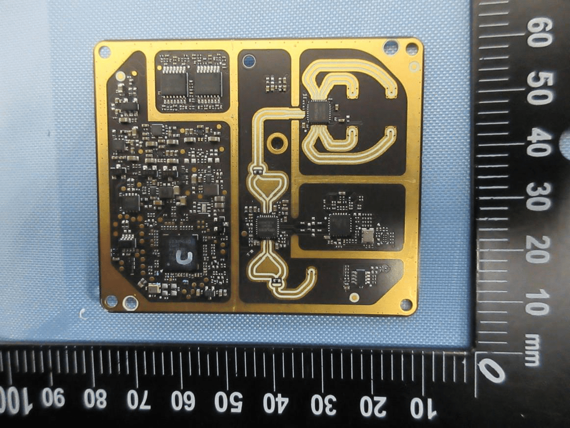
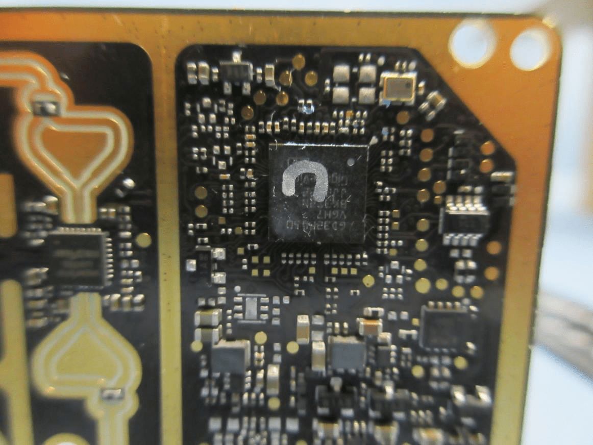
A close examination of the Upward Radar’s main PCB reveals a highly integrated design tailored for high-frequency radar operation. The central IC, likely an RF transceiver or dedicated radar SoC, anchors a densely populated board featuring several supporting chips for power management and signal processing. The black ENIG-finished PCB showcases controlled impedance traces and extensive via stitching around the RF section, highlighting a robust approach to EMI control. The upper right region’s gold-plated pattern forms an integrated PCB patch antenna, minimizing loss and maximizing signal integrity—ideal for 24 GHz operation. Power regulation is handled locally by large capacitors and an inductor, while a crystal oscillator provides precise timing. The overall assembly is compact, reliable, and optimized for UAV integration, demonstrating DJI’s emphasis on high-performance, low-EMI radar sensing.
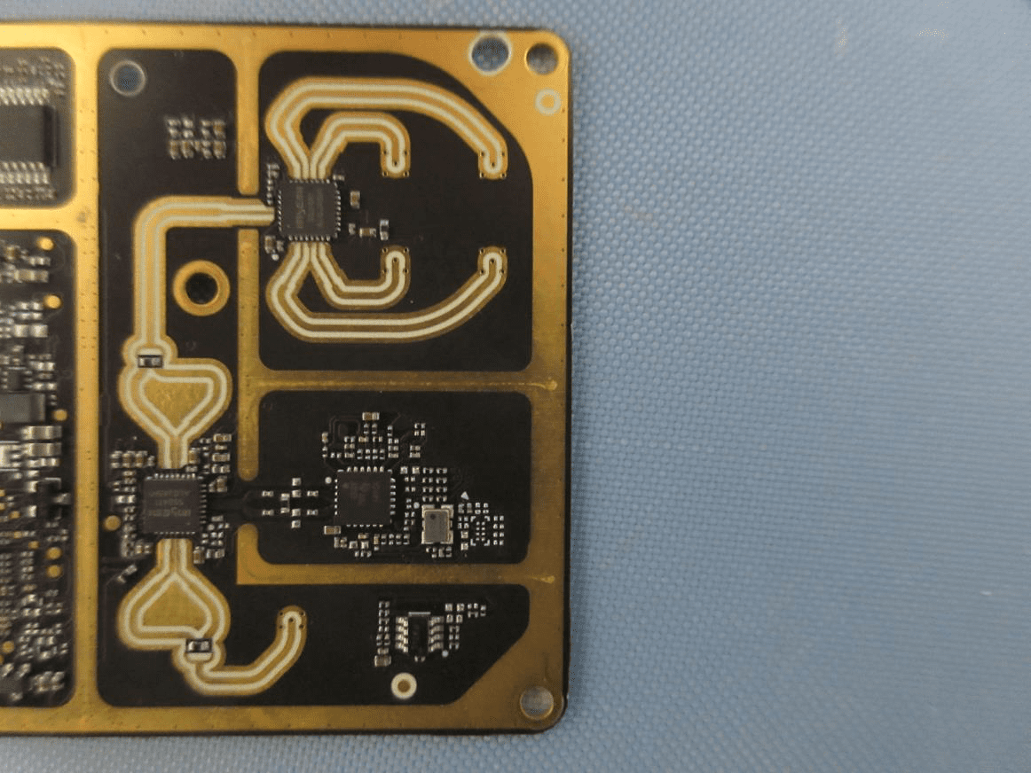
PCB Layout with Integrated Antennas and Shielded Enclosure
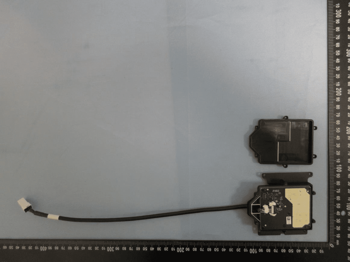
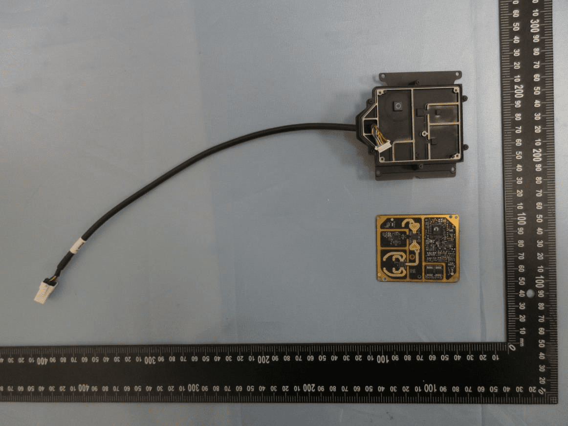
This image highlights the sophisticated PCB layout and modular assembly approach of the Upward Radar. The board features two major ICs—likely a microcontroller and an RF transceiver—supported by dense surface-mount components and local power regulation. The left side’s wide, curved traces and copper pours form PCB-integrated antennas, tailored for 24 GHz radar operation. A multi-wire cable harness provides shielded power and data connections, while the enclosure’s metal shielding compartments ensure robust EMI/RFI containment. The combination of high-density layout, integrated antennas, and modular cabling reflects a design optimized for both RF performance and serviceability, perfectly suited for drone and robotic platforms.
Densely Populated PCB with Advanced RF-Digital Separation
The internal architecture on display here underscores the Upward Radar’s commitment to signal integrity and compactness. A main SoC or RF transceiver anchors the bottom left, surrounded by supporting ICs for amplification and control. The right side is dominated by a complex PCB trace antenna, directly fed by the RF IC for minimal loss. The black ENIG-finished, multi-layer PCB demonstrates careful separation of analog/RF and digital domains, with via-in-pad and ground stitching to optimize EMI control. The absence of bulky connectors points to its role as an embedded sensor module, designed for seamless integration and high-frequency performance.
Antenna Array Integration and Signal Processing ICs
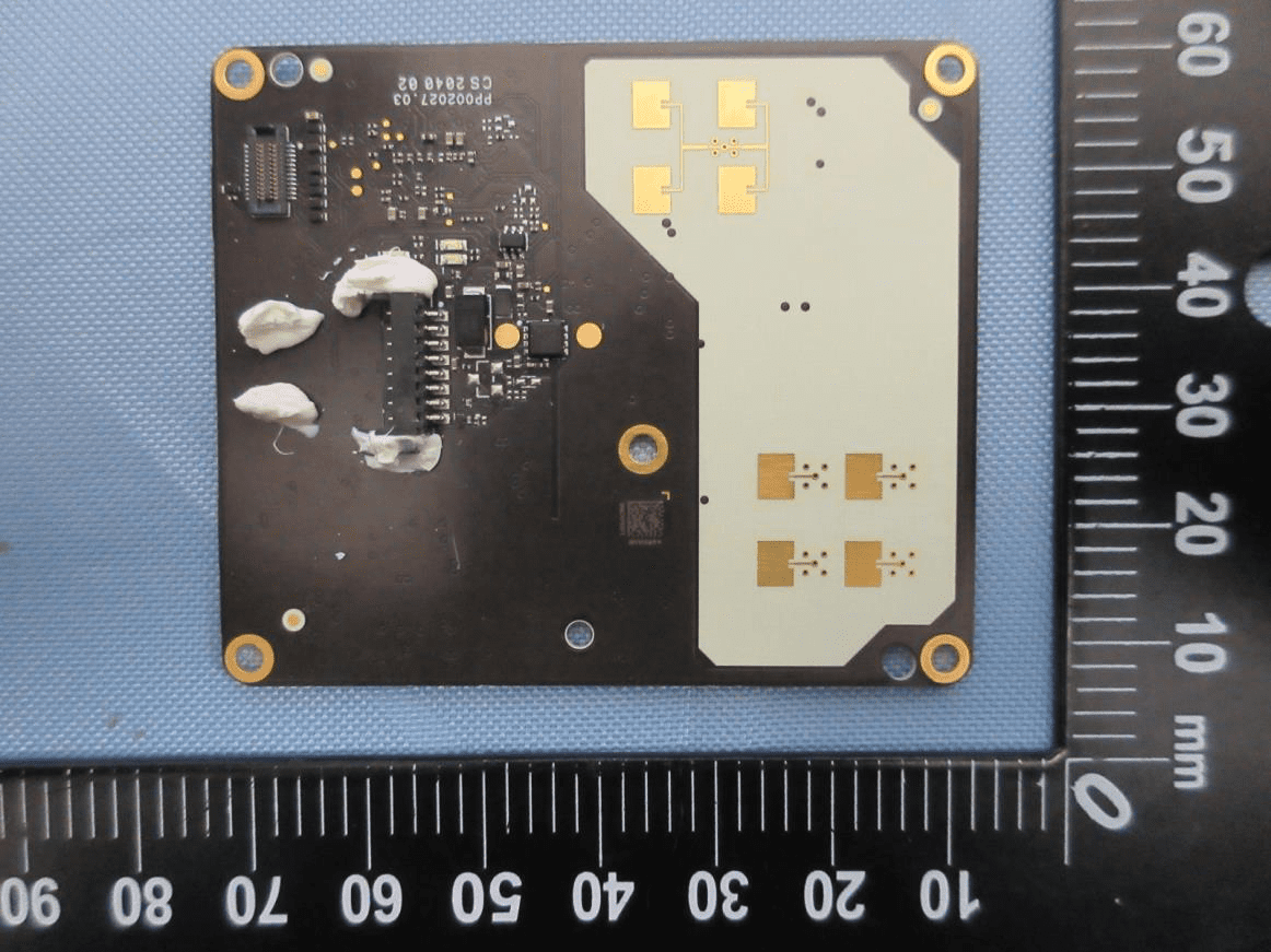
A closer look at this board reveals a sophisticated integration of a planar antenna array—likely a phased or MIMO configuration—on the right side, directly connected to the radar front-end. A large microcontroller or signal processing IC, partially stabilized with adhesive, manages radar operations, supported by smaller analog and power management chips. The black, multi-layer PCB features controlled impedance traces and robust grounding, optimized for 24 GHz radar sensing. The design’s modularity and separation of RF and digital sections reflect a high-performance, easily integrated radar module for UAVs or robotics.
Close-Up of Central RF SoC and Microwave Routing
This detailed view focuses on the heart of the radar module: a central IC, likely an RF transceiver or radar SoC, surrounded by precision-matched traces and dense surface-mount components. The left side’s wide, gold-plated traces form microwave transmission lines, feeding PCB-integrated antennas. The multi-layer, black ENIG PCB exhibits careful via stitching and ground pours, essential for maintaining signal integrity at 24 GHz. Local power regulation and crystal timing are evident, supporting low-noise, high-fidelity radar operation. The design’s compactness and RF-centric layout exemplify modern radar engineering for drone and robotic applications.
RF Front-End Featuring SG2401 RF IC and Controlled-Impedance Traces
This section showcases a specialized RF front-end IC labeled SG2401, likely a 2.4 GHz band device, surrounded by wide, curved microstrip traces for optimal high-frequency signal routing. The black ENIG PCB’s meticulous layout, with dense via stitching and minimal parasitics, ensures excellent signal integrity and EMI control. The absence of bulky components and reliance on PCB-integrated antennas or feedlines point to a miniaturized, performance-oriented design. This RF section is critical for transmitting and receiving radar signals, forming the backbone of the Upward Radar’s sensing capabilities.
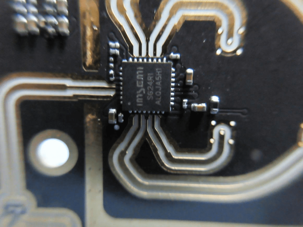
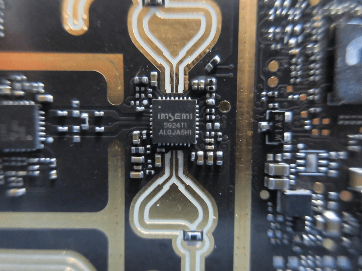
Radar Front-End with imsemi SG24T1 Transceiver and PCB Antenna Feeds
At the core of this section is the imsemi SG24T1 IC, a specialized mmWave or radar transceiver, surrounded by wide, gold-plated RF traces and dense via stitching. The PCB’s black ENIG finish, differential routing, and matched-length traces exemplify advanced RF design, supporting high-performance 24 GHz radar operation. The integrated antenna feedlines and absence of external connectors reinforce the module’s compact, integrated approach. This area manages both the transmission and reception of radar signals, underpinning the Upward Radar’s precision sensing capabilities.
Dual Planar Antennas and High-Density Component Placement
This view highlights a pair of planar PCB antennas, intricately fed by short, impedance-controlled traces from central RF ICs. The high-density, multi-layer black ENIG PCB features extensive ground pours and via stitching, ensuring robust EMI suppression. Supporting components—such as QFP/QFN-packaged ICs, local oscillators, and analog passives—are tightly integrated, reflecting a design focused on high-frequency radar performance, low noise, and system modularity. These antennas are key to the module’s ability to detect and track objects with high spatial accuracy.
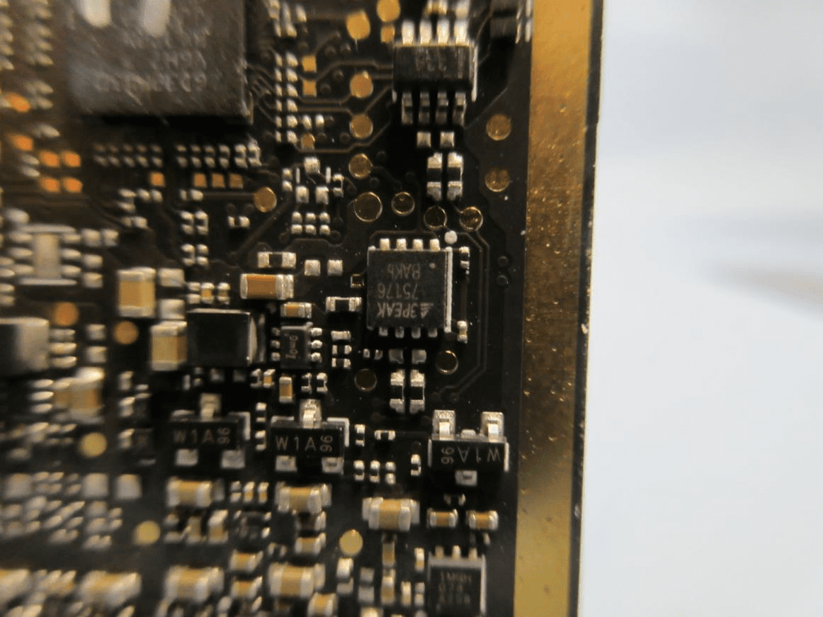
Dense RF/Analog Section with Gold-Plated Edge and Power ICs
A close-up of the PCB’s analog/RF section reveals a cluster of surface-mount devices, including an A3PEAK-marked IC (likely for power management or RF amplification) and several W1A transistors. The black PCB, with gold-plated edges and numerous vias, is optimized for signal integrity and EMI control. This area likely handles RF front-end or power regulation duties, supporting the sensitive radar circuitry nearby. The dense layout and premium finish indicate a design tuned for high reliability and minimal noise, critical for radar applications.
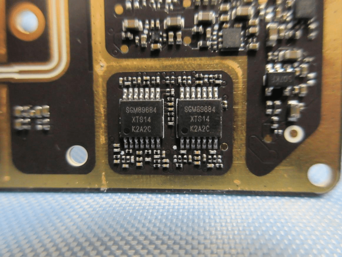
Analog Signal Processing Section with Dual Quad Op-Amps
This section focuses on dual SGM89684 quad op-amps, responsible for analog signal conditioning, buffering, or filtering of radar returns. The brownish-gold ENIG PCB features wide, controlled-impedance traces and robust ground pours, supporting low-noise, high-fidelity operation. The presence of parallel signal paths suggests multi-channel or differential processing, common in radar front-ends. Precise SMD placement and careful analog layout reflect a sophisticated approach to signal integrity, ensuring the radar’s measurements remain accurate and reliable.
Regulatory Insights & FCC Filing
The Upward Radar’s certification under FCC ID SS3-RD2414U is a testament to its adherence to stringent US standards for electromagnetic interference and RF emissions. This certification, registered by FCC.gov, is a prerequisite for legal sale, distribution, and operation of the device within the United States.
FCC filings for devices like the Upward Radar typically include:
- RF Exposure and EMC Test Reports:
Verifying that the device’s emissions are within safe and legal limits for both users and other electronics. - Internal and External Photographs:
Documenting the physical construction and component layout for compliance and traceability. - User Manuals and Operational Instructions:
Detailing proper usage, safety warnings, and integration guidelines. - Schematics and Block Diagrams:
Providing insight into the device’s architecture for regulatory review. - Labeling and Compliance Statements:
Ensuring end users are informed of FCC compliance and operational restrictions.
By achieving FCC certification, the Upward Radar is validated not only for performance but also for responsible spectrum usage and electromagnetic compatibility—a critical factor for widespread adoption in professional and consumer environments.
Potential Use Cases & Target Audience
The Upward Radar’s advanced sensing capabilities and robust design make it an excellent fit for a range of demanding applications:
-
UAV/Drone Obstacle Avoidance:
Integrated into aerial platforms, the radar provides real-time upward-looking collision detection, enabling drones to safely navigate complex environments or avoid overhead obstacles during autonomous or manual flight. -
Robotics and Industrial Automation:
Deployed on mobile robots or automated guided vehicles (AGVs), the radar enhances spatial awareness and safety, particularly in dynamic, cluttered, or low-visibility settings. -
Advanced Research and Prototyping:
Engineers and researchers can leverage the Upward Radar’s compact, modular design for developing next-generation navigation, mapping, or environmental sensing solutions in academic or commercial R&D projects.
The device’s high-frequency operation, integrated antenna, and compact footprint appeal to system integrators and engineers seeking reliable, easy-to-integrate sensing modules for advanced mobility or automation platforms.
Conclusion
The Upward Radar by SZ DJI TECHNOLOGY (Model: RD2414U, FCC ID SS3-RD2414U) stands out as a meticulously engineered radar sensor module, combining sophisticated RF design, robust EMI control, and compact integration. Its FCC certification underscores its compliance with US regulatory standards, ensuring both safety and reliability in demanding environments. Whether powering UAV obstacle avoidance, enhancing robotics, or enabling advanced research, the Upward Radar exemplifies the forefront of compact radar sensing technology—delivering precision, integration, and performance in a form factor primed for the future of autonomous systems.