Introduction
The Video Doorbell Wired from Ring LLC (Model: 5AT3T5) is a compact, always-powered smart doorbell designed to bring advanced security and connectivity to residential entryways. Engineered for seamless integration with existing doorbell wiring or an optional plug-in adapter, this device delivers high-definition video, real-time alerts, and reliable performance in a form factor built to withstand the elements.
A key milestone for any wireless device in the US market is FCC certification—and the Ring Video Doorbell Wired carries the designation FCC ID 2AEUPBHAGC001. This certification confirms that the device meets stringent regulations for radio frequency (RF) emissions and electromagnetic compatibility, making it legal for sale and installation across the United States. Beyond regulatory compliance, the FCC filing provides a unique window into the device’s wireless specifications, internal architecture, and engineering rigor.
In this article, we’ll examine the key features, technical specifications, wireless technology, and in-depth teardown analysis of the Ring Video Doorbell Wired. We’ll also explore what the FCC documentation reveals about its compliance and operational characteristics, offering an expert perspective for engineers, tech enthusiasts, and anyone interested in the inner workings of modern smart home devices.
Key Features & Specifications
The Ring Video Doorbell Wired is engineered for robust performance, safety, and continuous operation, making it a reliable choice for smart home security. Here’s a breakdown of its standout features and core technical specs:
Key Features
- Weather-Resistant Construction
- Tested to withstand water projected through a 6.3mm nozzle at 12.5 liters/minute and 30 kPa pressure from 3 meters for at least 3 minutes.
- Designed for reliable outdoor use in various weather conditions.
-
Not intended for underwater operation; must be charged only indoors in a dry state.
-
Power Flexibility
- Electrical Rating: Supports 10–24 VAC or 24VDC input, allowing compatibility with most standard doorbell systems or a dedicated power supply.
-
Optimized for continuous, wired power—no battery management required.
-
Operating Temperature Range
-
Temperature Rating: Engineered for environments from -5°F to 120°F (-20°C to 50°C), ensuring reliable function in both cold winters and hot summers.
-
Integrated Bluetooth
- Bluetooth support present (details not specified), likely used for initial setup or device pairing, enhancing ease of installation and integration with the Ring ecosystem.
Technical Specifications
- Electrical Input: 10–24 VAC or 24VDC
- Operating Temperature: -5°F to 120°F (-20°C to 50°C)
- Outdoor Use: Device is weather-resistant and suitable for permanent outdoor installation.
- Internal Power Management: Robust filtering and voltage regulation to ensure stability despite fluctuations from typical doorbell transformers.
Practical Benefits
- Easy Retrofit: Directly replaces most existing doorbell buttons, simplifying upgrades to smart video capabilities.
- Reliability: Wired design eliminates battery anxiety, providing always-on connectivity and faster response times.
- Safety: Must be installed and charged indoors in a dry state, adhering to safety guidelines outlined in the user manual.
- Durability: Weatherproofing and temperature tolerance allow for year-round operation in a variety of climates.
Operating Frequencies
The Ring Video Doorbell Wired (Model: 5AT3T5) operates on the following wireless frequencies, as specified in its FCC filing (FCC ID 2AEUPBHAGC001):
| Frequency Range (GHz) | Output Power (mW) | FCC Rule Part |
|---|---|---|
| 2.412–2.462 | 36 | 15C1 |
| 2.412–2.462 | 36 | 15C2 |
These frequencies correspond to the 2.4 GHz ISM band, commonly utilized for Wi-Fi and Bluetooth communications. The output power of 36 mW ensures adequate signal strength for reliable connectivity while remaining within regulatory limits for minimal interference. Adherence to FCC Rule Parts 15C1 and 15C2 underscores compliance with unlicensed wireless device standards in the United States.
Technology Deep Dive
The primary wireless technologies integrated into the Ring Video Doorbell Wired revolve around 2.4 GHz communications, which is the standard for most Wi-Fi and Bluetooth-enabled smart home devices. The presence of Bluetooth (as indicated in the specifications) likely facilitates initial setup and device pairing, streamlining installation for end users. The main data and video transmission are expected to occur over Wi-Fi, leveraging the 2.4 GHz band for broad compatibility with home networks.
Operating within the 2.4 GHz spectrum offers several advantages: robust signal penetration through walls and typical home construction, widespread support across routers and access points, and resilience to most environmental interference. The specified output power of 36 mW is a balanced choice—high enough for reliable range across a typical household, yet low enough to minimize RF emissions and power consumption, in line with FCC requirements.
From an engineering standpoint, the internal test reports referenced in the FCC filing confirm that the device maintains compliance with RF exposure and electromagnetic compatibility limits. Careful PCB layout, shielding, and power management—evident in the teardown analysis—further contribute to the device’s reliable wireless performance, even in environments crowded with other 2.4 GHz devices.
In-Depth Internal Component Analysis / Teardown
Mainboard and Camera/Sensor Assemblies
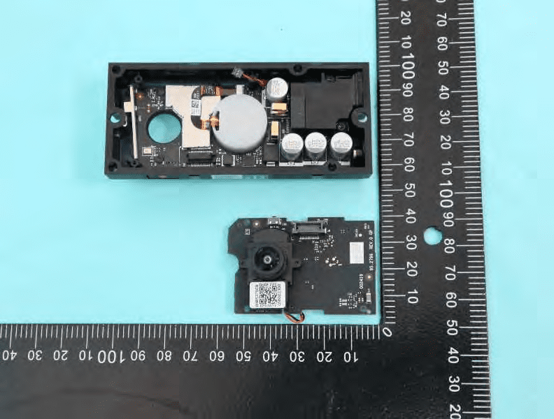
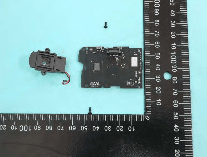
The internal architecture of the Ring Video Doorbell Wired reveals a sophisticated, modular design. The main PCB, still partially housed, is densely populated with surface-mount components, indicative of a high-density, multi-layer construction. A prominent metal shield protects what is almost certainly the main system-on-chip (SoC) or MCU, responsible for orchestrating video processing, networking, and device control. The adjacent camera/sensor board features a compact lens and image sensor module, with a supporting IC likely handling image signal processing. Connections between the two boards are managed via FPC/FFC connectors, ensuring high-speed, noise-resistant data transfer. Power management is robust, with multiple large capacitors and a significant inductor providing efficient voltage regulation. The modular board separation facilitates both assembly and potential repair, while the dense layout and extensive EMI shielding underscore a focus on wireless performance and reliability.
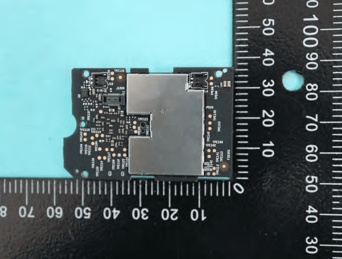
Main PCB Overview with Scale Reference
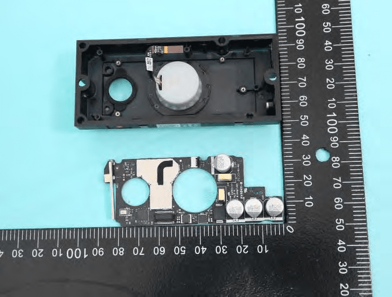
A closer look at the main PCB highlights its custom shape and compact, highly integrated layout. The central IC, presumed to be the SoC or main MCU, sits beneath a metal shield for EMI suppression. Surrounding this are memory chips, power management ICs, and possibly a dedicated Wi-Fi transceiver. The board’s layout reflects clear separation between power, RF, and digital domains, with large electrolytic capacitors providing ample filtering for the main supply. The presence of a large cylindrical component suggests a built-in speaker or chime, while visible FPC connectors allow for modular assembly. The use of robust shielding and high-density component placement demonstrates a design optimized for size, cost, and wireless integrity.
PCB with Shielded SoC and Power Filtering
This image provides a detailed view of the main PCB, emphasizing the importance of power integrity and RF shielding. The large metal can covers the main processing and RF sections, minimizing electromagnetic interference. Three prominent 220μF capacitors ensure stable voltage delivery, while smaller power management ICs and inductors handle efficient conversion from the doorbell transformer’s AC or DC input. The compact, multi-layer design and dense component placement indicate a mature, cost-optimized approach. Spring-loaded pogo pins in the lid suggest provisions for factory testing or programming, further reflecting attention to manufacturing quality and device reliability.
Close-Up of Flash Memory and EMI Shielding
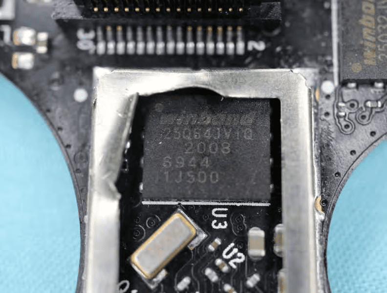
This section of the PCB spotlights a Winbond 25Q64FV1Q serial flash memory (8MB), likely used for firmware storage, surrounded by robust EMI shielding. The use of a crystal oscillator nearby provides a stable clock source for the SoC or wireless subsystem, critical for timing-sensitive operations. The fine-pitch FPC connector enables high-speed interfacing with other modules, such as the camera. The dense layout, with extensive ground pours and via structures, ensures both signal integrity and EMI containment, supporting reliable wireless communication in a compact form factor.
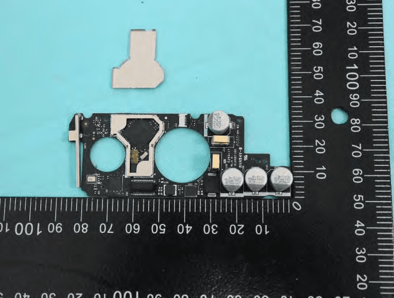
Camera Module and Video Processing Section
Here, the focus shifts to the camera module and its supporting PCB. The main IC, likely an image processor or SoC, manages real-time video capture and processing. The use of a modular FPC connector allows the camera to be easily integrated or replaced, enhancing assembly efficiency and serviceability. While no shielding is visible on this side, careful PCB layout and ground plane usage help mitigate RF interference. Test points and passive components facilitate manufacturing diagnostics and ensure stable operation, while the overall compactness reflects the demands of a video-centric IoT device.
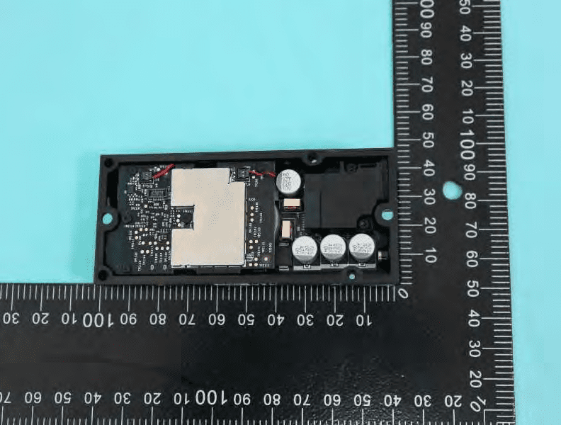
Main PCB Power Section and Antenna Connections
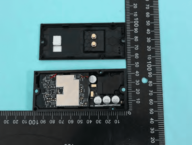
This view of the PCB highlights the critical power supply section, with four large electrolytic capacitors and multiple inductors ensuring stable voltage regulation. The central shielded area houses the primary SoC and RF components, while two thin red wires—likely antenna leads—enter the shielded section, pointing to internally integrated 2.4GHz Wi-Fi/Bluetooth antennas. The layout demonstrates solid grounding and EMI control, vital for maintaining wireless performance and device reliability in real-world installations.
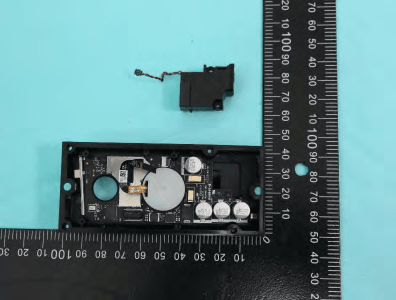
Exposed SoC and Power Section after Shield Removal
With the EMI shield removed, the main SoC or MCU is exposed, surrounded by supporting memory and power management ICs. The right side of the PCB is dominated by large capacitors and an inductor, forming the core of the device’s power regulation circuitry. Multiple test points and connectors facilitate diagnostics and modular assembly. The overall arrangement, with high component density and careful signal routing, is characteristic of a well-engineered consumer IoT device focused on wireless connectivity and video processing.
Speaker/Buzzer and Modular Connections
This section displays the main PCB alongside a detached speaker or buzzer module, connected via a wire harness. The central IC, shielded by a round metallic can, likely orchestrates video, audio, and network functions. Surrounding power management and memory ICs, along with extensive decoupling, ensure stable operation. The presence of FPC connectors and test points supports modular assembly and manufacturing diagnostics. The design combines high integration with modularity, facilitating both performance and efficient production.
Shielded Mainboard with Dense Surface-Mount Components
The final image reveals a compact, green PCB with a large, centrally placed metal shield, under which the main SoC and RF sections reside. Multiple FPC connectors at the edge enable connections to peripherals like the camera or microphone. The presence of numerous test points and surface-mount passives speaks to a design optimized for automated assembly and quality control. The overall density and robust shielding underscore the device’s focus on reliable RF performance and manufacturability.
Regulatory Insights & FCC Filing
The FCC ID 2AEUPBHAGC001 assigned to the Ring Video Doorbell Wired signifies the device’s full compliance with US regulations for electromagnetic compatibility and RF emissions. Registration with the FCC is a legal prerequisite for any wireless device sold in the United States, confirming that the product does not interfere with other electronic equipment and operates safely within prescribed limits.
FCC filings provide a wealth of technical and compliance information, including laboratory test reports, user manuals, internal photographs, block diagrams, and schematics. These documents detail how the device performs under various operating conditions, ensuring that it meets standards for RF exposure, electromagnetic interference, and safe operation.
According to internal documentation and the user manual, the Ring Video Doorbell Wired is intended to replace an existing doorbell button, drawing wired power either from a traditional doorbell transformer or an optional plug-in adapter. The manual provides critical safety guidance, electrical requirements, and environmental ratings, emphasizing proper installation and usage. The FCC test reports confirm that the device’s emissions stay within permissible limits for unlicensed wireless devices, and that its internal shielding and power management are engineered to prevent interference with other household electronics.
Potential Use Cases & Target Audience
The Ring Video Doorbell Wired is designed for a wide range of practical scenarios, catering to homeowners and property managers seeking reliable, always-on entryway security:
- Smart Home Upgrades: Ideal for tech-savvy homeowners looking to retrofit their existing doorbell system with video and smart notification capabilities, without the hassle of battery maintenance.
- Rental Properties: Suited for landlords or property managers who want to enhance security and monitor visitor activity at rental units, leveraging the device’s easy installation and robust weather resistance.
- Urban and Suburban Residences: Perfect for apartments, condos, and single-family homes where continuous monitoring, reliable wireless connectivity, and integration with broader smart home ecosystems are priorities.
With its combination of wired reliability, advanced wireless technology, and weatherproof engineering, the Ring Video Doorbell Wired meets the needs of users who demand both convenience and peace of mind.
Conclusion
The Ring Video Doorbell Wired (Model: 5AT3T5, FCC ID 2AEUPBHAGC001) exemplifies the modern smart home device—compact, reliable, and meticulously engineered for security and performance. Its FCC certification confirms compliance with stringent US wireless and EMI standards, enabling legal sale and installation nationwide. Through a blend of robust power management, advanced video processing, and careful RF design, it delivers seamless connectivity and dependable operation in all seasons. For homeowners and professionals alike, the Video Doorbell Wired stands as a testament to how thoughtful engineering and regulatory diligence converge to create a superior smart home experience.