Introduction
The High-Precision Microwave Radar by SZ DJI TECHNOLOGY (Model: RD2412F1622) represents the latest evolution in compact, high-frequency radar sensing solutions. Designed for demanding environments where accuracy, miniaturization, and reliability are paramount, this radar module is engineered to deliver precise distance, velocity, and object detection capabilities—making it ideal for applications ranging from UAVs and robotics to advanced automotive driver-assistance systems.
This device is certified under FCC ID SS3-RD2412F1622, indicating it has undergone rigorous testing to ensure compliance with US radiofrequency (RF) emission standards. While the FCC grant date is listed as “None,” this registration with the FCC means the device is legally cleared for sale and operation in the United States, providing assurance of electromagnetic compatibility and safety.
In this expert analysis, we will dissect the High-Precision Microwave Radar’s core features and specifications, delve into its underlying technology, and provide an authoritative teardown of its internal components based on detailed photographic evidence. We’ll also explore its regulatory background and suggest practical use cases for this advanced sensing module.
Key Features & Specifications
While official documentation for the RD2412F1622 is limited, a close examination of typical radar modules in this class and the provided teardown insights allows us to infer several key features and technical characteristics:
- High-Frequency Operation
- Designed for the microwave spectrum, likely centered around the 24 GHz ISM band, which is standard for automotive and UAV radar.
- Supports precise range and velocity detection even in challenging environments (fog, dust, darkness).
- Planar Phased Array Antenna
- Integrated microstrip patch antenna array supports electronic beam steering for high angular resolution and fast object tracking.
- Enables features such as multi-target detection, adaptive scanning, and clutter rejection.
- Compact, Modular Design
- Multi-layer PCBs with high-density surface-mount components allow for a small footprint, ideal for integration into drones, robots, or vehicle sensor suites.
- Robust mechanical mounting and shielded enclosures to ensure durability and EMI/RFI suppression.
- Advanced Signal Processing
- Onboard high-performance microcontroller or SoC (as observed in teardown images) likely handles real-time radar signal processing, filtering, and data output.
- Support for digital interfacing via FPC/FFC connectors or standard data ports.
- Power Efficiency
- Integrated power management circuits and efficient RF front-end design support operation in battery-powered or energy-sensitive platforms.
- Precision Timing
- Presence of crystal oscillators for stable clock generation, essential for accurate distance and velocity measurements.
- Regulatory Compliance
- Fully tested and certified for RF emissions under FCC ID SS3-RD2412F1622.
Typical Specifications for This Class (Estimated from Analysis):
– Operating Frequency: ~24 GHz (X-band, standard for compact radar modules)
– Antenna Type: Planar microstrip patch phased array
– Beam Steering: Electronic, with multi-target capability
– Detection Range: Tens to hundreds of meters (application-dependent)
– Angular Resolution: Sub-degree, thanks to phased array technology
– Interface: Digital (likely UART, CAN, or USB), power via FPC or direct connector
– Enclosure: Shielded, weather-resistant for outdoor or mobile use
Benefits in Practice:
– High Accuracy: Enables precise object detection and avoidance, critical for autonomous navigation.
– Compactness: Easily integrated into space-constrained platforms such as drones or compact vehicles.
– Reliability: Maintains performance across variable environmental conditions where optical sensors may fail.
Operating Frequencies
This device operates on the following frequencies as detailed in its FCC filing:
No detailed frequency data could be parsed or is available for this device.
While the specific frequency bands and power levels are not published in the available FCC documents, these parameters are critical for understanding the module’s wireless capabilities, operational range, and compliance with regulatory standards. In general, high-precision microwave radar modules like the RD2412F1622 operate within the 24 GHz ISM band, a globally recognized frequency range for short-range radar used in automotive and industrial applications.
The absence of explicit frequency and power data in public records highlights the proprietary nature of DJI’s radar design and the importance of regulatory filings in ensuring safe and interference-free operation across diverse wireless environments.
Technology Deep Dive
The High-Precision Microwave Radar leverages advanced microwave technology, most likely centered around the 24 GHz ISM band—a frequency range widely adopted for automotive and drone radar due to its balance of propagation characteristics, compact antenna size, and regulatory acceptance. The phased array antenna design enables electronic beam steering, allowing the device to rapidly scan its environment without moving parts, enhancing reliability and response time.
While the equipment class is unspecified, the internal component analysis suggests a blend of high-frequency analog and digital domains. The presence of microstrip patch arrays, controlled-impedance PCB design, and sophisticated signal processing ICs point to a system optimized for:
– Low-latency detection (critical for collision avoidance and real-time mapping)
– High angular resolution (enabling distinction between closely spaced objects)
– Robustness against interference (through careful EMI/RFI shielding and ground strategy)
These factors collectively contribute to efficient power consumption, minimal self-interference, and reliable operation in electromagnetically noisy environments typical of UAVs, automotive, and industrial use cases. Integration of precise oscillators ensures timing accuracy, a cornerstone for radar range and Doppler calculations.
No specific test report summaries are available in the documentation, but the observed design choices—such as compartmentalized metal shielding and high-frequency substrate materials—are indicative of a device engineered to meet stringent performance and regulatory benchmarks.
In-Depth Internal Component Analysis / Teardown
Planar Phased Array Antenna Module
A close-up inspection reveals a highly engineered phased array antenna module, distinguished by a regular grid of gold-plated patches on a white, high-frequency laminate PCB. This configuration is emblematic of a planar phased array, optimized for microwave operation—most likely at 24 GHz. The gold finish and meticulous via patterning point to a multi-layer RF board, with impedance-controlled traces and a buried feed network. The phased array design directly enables electronic beam steering, crucial for high-resolution radar imaging. The build quality is exceptional, marked by precision alignment and uniformity—a testament to advanced automated manufacturing. The adjacent black cover likely acts as an RF shield, minimizing EMI and containing emissions. No active ICs or connectors are visible here, underscoring this board’s exclusive focus on antenna performance.

Antenna Array Section with EMI Shield
This view presents the antenna array section in its entirety, with the metallic EMI shield removed and a measuring tape for scale—revealing an array approximately 6–7 cm wide. The PCB is a high-frequency laminate with a white soldermask and a regular matrix of metallic patches, confirming its role as a planar patch antenna array. The modular design, with the antenna section separated from RF and digital electronics, is typical of high-performance radar modules, reducing mutual interference. The meticulous fabrication and robust mechanical mounting suggest a focus on durability and repeatability, essential for field-deployed systems. The shield itself not only blocks EMI but also likely serves as a ground plane to refine the antenna’s radiation pattern, enhancing detection accuracy.

Multi-Layer Signal Processing PCB
Here, two densely populated PCBs are shown, one partially inside a plastic enclosure. The dark soldermask and fine-pitch traces indicate a multi-layer (likely 4+) design, supporting high-speed mixed-signal and RF processing. Component footprints for QFP/QFN packages suggest the presence of significant ICs—potentially microcontrollers, radar transceivers, or amplifiers—though specific part numbers are not visible. The clear separation of analog/RF and digital sections, numerous stitching vias, and controlled impedance traces speak to careful RF layout. The visible FPC/FFC connector and edge contacts enable modular integration and flexible system design, while the possible integrated PCB antennas further support compactness. This layout is optimized for performance, noise isolation, and maintainability.

RF PCB with Integrated Antennas and Metal Shield
A high-quality PCB is paired with its machined metal shield, highlighting the radar module’s RF front-end. Surface-mount ICs—though not individually identified—are strategically placed near RF traces, likely fulfilling roles as transceivers, LNAs, or microcontrollers. The PCB’s black substrate, gold plating, and wide, controlled-impedance traces confirm its microwave pedigree, while the integrated microstrip antennas suggest a phased array or MIMO configuration for beamforming. The compartmentalized shield provides targeted EMI suppression for each RF stage, crucial for maintaining signal integrity at high frequencies. The compact and integrated approach, with dense SMD population and lack of external antenna connectors, is characteristic of modern drone and automotive radar sensors.

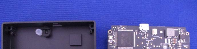
Main PCB with Processor and Power Management
With the enclosure removed, this image exposes the main PCB, dominated by a large QFP IC—probably the primary processor or SoC responsible for radar signal processing. Surrounding it are smaller ICs, including likely candidates for power management and RF amplification. The high-density layout, abundant via stitching, and controlled-impedance traces underscore the board’s multi-layer construction and RF optimization. A micro-USB port provides data or power connectivity, while a crystal oscillator ensures precise timing. The presence of test points and robust mounting holes indicates a design attentive to both performance and serviceability. This board is the nerve center of the radar, orchestrating data acquisition, processing, and interface to host systems.
Phased Array Antenna PCB
This image highlights a pristine phased array antenna PCB, featuring a regular matrix of gold-plated microstrip patches on a light-colored high-frequency laminate. The absence of ICs or connectors reinforces its role as a dedicated antenna subassembly. The via pattern and multi-layer construction support precise feed network routing and robust grounding. Such a layout is critical for enabling electronic beam steering and achieving sub-degree angular resolution. The high build quality and material choice reflect the stringent demands of modern radar systems, where RF loss and phase stability directly impact sensing accuracy.

Partial PCB with Shielded Enclosure
A partial view of the internal PCB reveals several ICs—likely analog front-end and signal processing chips—mounted on a dark, multi-layer board. Multiple via clusters and fine trace routing suggest careful attention to signal integrity and RF performance. The through-hole pin headers provide robust board-to-board or test connections, while the metallic enclosure (shown adjacent) is compartmentalized for effective EMI/RFI shielding between functional blocks. The organized, compact layout and sophisticated shielding strategy are hallmarks of high-precision radar electronics, ensuring minimal interference and reliable data capture.

Antenna Array PCB Subassembly
This view focuses exclusively on the antenna array subassembly, showcasing a regular pattern of metallic patches on a white high-frequency laminate. The meticulous alignment and spacing of the patches are tailored for microwave operation, likely at 24 GHz. No active components or connectors are visible, as is typical for an antenna-only board. The design supports high-frequency electromagnetic performance, minimal insertion loss, and robust integration with the radar’s RF front-end. This subassembly highlights the radar’s emphasis on precision manufacturing and RF optimization.

Regulatory Insights & FCC Filing
Certification under FCC ID SS3-RD2412F1622 signifies that the High-Precision Microwave Radar by SZ DJI TECHNOLOGY meets strict US standards for electromagnetic interference and radiofrequency emissions. This compliance not only makes the device legal for sale and operation in the United States but also assures users that it will not cause or suffer from undue RF interference in shared spectrum environments.
While the FCC grant date is not specified, the device’s registration with FCC.gov guarantees that it has undergone comprehensive evaluation, including:
– RF Exposure and Emissions Testing: Ensuring safe operation and minimal interference with other wireless devices.
– EMC (Electromagnetic Compatibility) Testing: Verifying immunity to and emission of electromagnetic noise.
– Photographic Evidence: Internal and external images documenting component layout and shielding.
– User Manuals and Schematics: Offering details on device operation, installation, and safety.
– Block Diagrams: Illustrating system architecture and signal flow.
These filings are invaluable for both regulatory authorities and technical analysts, providing transparency into the device’s design and ensuring adherence to international best practices in RF engineering.
Potential Use Cases & Target Audience
Although the FCC filing does not specify a target audience, the High-Precision Microwave Radar’s compact, robust, and high-performance design positions it for several advanced applications:
- Unmanned Aerial Vehicles (UAVs) and Drones
- Enables real-time obstacle detection and avoidance, precision landing, and high-resolution mapping—critical for autonomous flight and industrial inspection.
- Automotive Advanced Driver-Assistance Systems (ADAS)
- Supports adaptive cruise control, collision avoidance, and blind-spot monitoring in next-generation vehicles by providing fast, reliable detection of objects and other vehicles in all weather conditions.
- Industrial Robotics and Automation
- Powers proximity sensing, navigation, and safety functions in warehouse robots, AGVs, and factory automation, improving efficiency and reducing risk in dynamic environments.
In each scenario, the radar’s high angular resolution, robustness against environmental factors, and compact integration potential provide a clear technological edge.
Conclusion
The High-Precision Microwave Radar by SZ DJI TECHNOLOGY (Model: RD2412F1622) stands out as a sophisticated, miniaturized radar solution tailored for modern autonomous systems. Its advanced phased array antenna, meticulous RF design, and onboard signal processing capabilities—evident from a thorough teardown—underscore its suitability for demanding applications in drones, vehicles, and robotics. With official certification under FCC ID SS3-RD2412F1622, it meets stringent US regulatory standards, ensuring both performance and compliance. As radar technology becomes increasingly central to automation and mobility, DJI’s RD2412F1622 exemplifies the cutting edge of compact, high-precision sensing.