Introduction
The M1P by SZ DJI TECHNOLOGY CO., LTD. stands at the intersection of advanced aerial technology and robust wireless engineering. Engineered as a compact yet powerful drone platform, the M1P integrates sophisticated flight control, high-resolution imaging, and seamless remote operation—making it a compelling choice for both enthusiasts and professionals. Central to its legitimacy and market readiness is its FCC certification under FCC ID SS3-M1P1607. While the grant date is currently listed as ‘None’, this registration confirms the device’s compliance with stringent US RF emission standards, signifying its eligibility for sale and operation in the United States.
In this article, we’ll dissect the M1P from the ground up: exploring its key features, technical specifications, wireless and RF capabilities, internal hardware architecture, and the regulatory framework that underpins its deployment. Whether you’re an engineer, drone aficionado, or simply curious about the technology behind modern UAVs, this comprehensive teardown and analysis will offer deep insights into what makes the M1P a standout in its class.
Key Features & Specifications
The M1P’s design philosophy centers on delivering a feature-rich, reliable, and user-friendly drone experience. Below, we expand on its core capabilities and technical underpinnings:
Key Features
-
DJI GO App Compatibility:
Seamless integration with the DJI GO mobile application enables intuitive flight control, camera operation, and real-time telemetry—empowering users with full situational awareness and control. -
Vision Positioning Sensors:
Advanced downward-facing sensors enhance stability and precise hovering, especially indoors or in GPS-denied environments. -
Gimbal: Controllable Pitch Range -90° to +30°:
The 3-axis gimbal allows for smooth, stabilized footage and flexible camera angles, crucial for capturing dynamic aerial shots. -
Burst Shooting & HDR Photo Modes:
Capture fast action sequences or high-contrast scenes with advanced photography modes, ensuring crisp, detailed imagery under challenging conditions. -
Micro SD Card Slot (Max 64 GB, Class 10 or UHS-1):
Supports high-speed storage for 4K video and high-resolution photos, minimizing buffering and maximizing recording duration. -
Remote Controller with Rechargeable Battery:
Offers extended flight sessions and reliable connectivity, with built-in battery management for convenience. -
Time-lapse:
Automated time-lapse functionality enables creative, cinematic video sequences with minimal setup.
Technical Specifications
-
Max Ascent Speed: 5 m/s
Enables swift elevation changes, useful for dynamic filming and obstacle avoidance. -
Obstacle Sensory Range: 2–49 ft (0.7–15 m)
Enhances safety and collision avoidance during complex maneuvers. -
Supported SD Card Types: Micro SD, up to 64 GB (Class 10/UHS-1)
Ensures compatibility with high-performance storage solutions. -
Max Transmission Distance:
- FCC: ~7 km
-
CE: ~4 km
Unobstructed, interference-free environments. -
Operating Temperature Range: 32° to 104° F (0° to 40° C)
Designed for reliable operation in a wide range of climates. -
Remote Controller Operating Frequency: 2.400–2.483 GHz
Utilizes globally available ISM bands for robust wireless communication. -
Max Service Ceiling Above Sea Level: 19,685 ft (6,000 m)
Software altitude limit: 400 ft above take-off point (adhering to aviation regulations). -
Satellite Systems: GPS/GLONASS
Dual-satellite support for enhanced positioning accuracy and reliability.
Additional Extracted Specifications
-
Wi-Fi: 2.400–2.483 GHz
High-speed wireless connectivity for FPV and telemetry. -
Bluetooth: Present (details not specified)
Likely used for device pairing and auxiliary functions. -
Camera:
- Max Image Size: 4000×3000 (12 MP)
- Video Modes:
- UHD: 4096×2160 (4K) 24/25p
- 3840×2160 (4K) 24/25/30p
- 2704×1520 (2.7K) 24/25/30p
- FHD: 1920×1080 24/25/30/48/50/60/120p
- HD: 1280×720 24/25/30/48/50/60p
-
Sensor: 1/2.3” CMOS, 12 MP effective pixels
-
Battery:
- Max Flight Time: Approx. 25 minutes
- Voltage: 11.4 V
- Energy: 43.6 Wh
- Weight: ~235 g
- Intelligent Flight Battery Capacity: 3,830 mAh
Operating Frequencies
The M1P, under FCC ID SS3-M1P1607, operates across several critical wireless frequency bands. These frequencies, as documented in the FCC filing, define its communication, control, and video transmission capabilities:
| Frequency Range (GHz) | Output Power (mW) | FCC Rule Part |
|---|---|---|
| 2.462 | 260 | 15CCC |
| 2.4725 | 908 | 15CCC1.42.412 |
| 2.4775 | 719 | 15CCC1.32.4105 |
| 12.4035–2.4775 | 912 | 15CCC1.22.4055 |
| 15.18–5.24 | 38 | 15E38 |
| 15.745–5.825 | 27 | 15E38 |
These bands, primarily in the 2.4 GHz and 5 GHz ranges, are widely used for high-throughput, low-latency data transfer—supporting both remote control and HD video streaming. The output power levels ensure a balance between range, penetration, and regulatory compliance.
Technology Deep Dive
The M1P’s wireless architecture leverages both Wi-Fi (2.4 GHz ISM band) and Bluetooth for seamless connectivity between the drone, remote controller, and user devices. The absence of cellular modules (Equipment Class: None) means all communication is local, reducing latency and enhancing user privacy.
Operating within the 2.4 GHz and 5 GHz bands allows the M1P to achieve impressive transmission distances—up to 7 km under FCC regulations—while maintaining robust resistance to interference. The device’s variable output power across frequencies ensures compliance with regional RF exposure limits and optimizes battery life. Higher output at 2.4 GHz supports long-range control and video downlink, while lower-power 5 GHz bands can help minimize interference in crowded RF environments.
The integration of GPS/GLONASS further augments situational awareness and flight stability. Advanced power management and EMI shielding, as evidenced in teardown photos, ensure that high-speed data and RF subsystems operate harmoniously without cross-interference—a testament to DJI’s engineering rigor.
In-Depth Internal Component Analysis / Teardown
Main Processor and RF Subsystems
A densely populated PCB section reveals the heart of the M1P’s computational and wireless prowess. Multiple large integrated circuits, some enveloped in metal EMI shields, suggest the co-location of the main processor, memory, and RF transceivers. The high layer count and fine-pitch traces indicate a sophisticated multi-layer design, optimized for signal integrity and low noise. Power regulation is robust, with sizeable inductors and capacitors ensuring clean voltage rails for sensitive analog and digital circuits. The presence of a small white connector hints at modularity, enabling easy interfacing with other subsystems or antennas. Overall, the build quality and layout reflect DJI’s commitment to high-performance, reliable drone electronics.

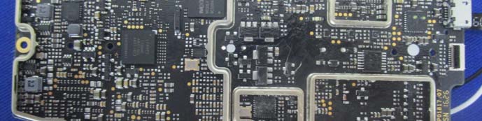
System Control and Memory Architecture
This section of the PCB showcases several large ICs, likely serving as the main controller (SoC or MCU) and memory modules. The use of both QFP and BGA packages points to a mix of high-integration digital logic and fast-access memory. Extensive EMI shielding covers critical sections, highlighting the device’s RF sensitivity and regulatory compliance. The presence of differential pair routing and dense power regulation components supports high-speed data processing and robust wireless communication. Modular FPC/FFC connectors facilitate inter-board communication, while test points aid diagnostics—a hallmark of a well-engineered, serviceable product.
Modular Controller and Edge Connectivity
A closer look at another PCB segment, measured for scale, reveals intricate component placement and sophisticated signal routing. Numerous gold-plated edge contacts and test points underline a modular design, enabling efficient manufacturing and flexible subassembly replacement. The multi-layer construction, with abundant vias and copper pours, supports both power integrity and high-speed data transmission. Metal shield outlines further indicate the strategic placement of sensitive RF or digital sections. This board likely serves as a main controller or communication hub, balancing compactness with the need for robust wireless and sensor integration.

Antenna Integration and Power Management
This PCB assembly features a U.FL coaxial connector, confirming support for external or remote antennas—a critical factor for maximizing wireless range and minimizing interference. The green, matte-finish board is densely populated with both large processing ICs and supporting components. Multiple FPC/FFC connectors and a micro-USB port provide versatile interfacing options, while extensive EMI shielding and robust power regulation ensure reliable operation in challenging RF environments. The compact, modular layout underscores DJI’s focus on high performance and serviceability in a constrained form factor.

Sensor Fusion and Advanced Flight Control
A striking aspect of this PCB is the inclusion of two mesh-covered circular components, likely ultrasonic transducers for obstacle detection or altitude sensing. The board’s layout is dominated by BGA and QFN ICs—presumed to be the main SoC, memory, and RF chips—protected by soldered metal shields. The presence of a U.FL connector confirms external antenna support. Multiple high-density FPC connectors and debug points facilitate modular assembly and diagnostics, while the extensive EMI shielding and power regulation highlight the board’s role in managing sensitive flight and sensor data.

Power Regulation and RF Subsystem
This PCB segment features a prominent metal shield over a large IC, likely responsible for RF or high-speed digital processing. The board’s black soldermask, dense via structure, and careful component placement point to a multi-layer, high-quality design. Edge-mounted connectors enhance modularity, supporting flexible connections to batteries, sensors, or antennas. Large inductors and capacitors suggest robust power regulation, vital for maintaining stability across various drone subsystems. The visible test points and conformal coating further reinforce the product’s durability and serviceability.

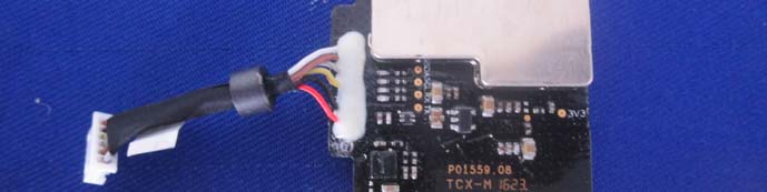
Shielded Communication Module
This internal view highlights a section dominated by a large metal EMI shield, covering what is likely the main SoC or RF transceiver. A multi-colored wire harness connects via a secured white connector, ensuring mechanical robustness and reliable power or data transmission between modules. The black PCB and numerous test points reflect high build quality and attention to EMI control. The compact, modular design is tailored for easy assembly and replacement, supporting the M1P’s high-frequency, low-noise communication requirements.
Gimbal or Sensor Control Board
This assembly pairs a dense black PCB with an adjacent mechanical component—possibly a gimbal or motor assembly. The board features surface-mount ICs for sensor interfacing or control logic, with a flex cable connector enabling integration with other modules. The absence of large RF shields suggests this is a control or sensor board, rather than a main communications platform. High-quality layout, power regulation, and modular interconnects reflect DJI’s engineering rigor, supporting precise stabilization and sensor fusion for reliable flight performance.

Shielded RF/High-Speed Digital Section
This close-up reveals a green PCB with a visible metal EMI shield and a flex cable (FPC) connector, indicative of a high-density, modular assembly. The shielded area likely houses sensitive RF or high-speed digital ICs, while the FPC interface supports connection to other critical modules, such as cameras or antennas. The meticulous assembly and robust grounding underscore the device’s emphasis on EMI/RFI control, ensuring stable operation of wireless and high-speed digital subsystems.

Regulatory Insights & FCC Filing
The FCC ID SS3-M1P1607 is a critical marker of the M1P’s compliance with US electromagnetic interference (EMI) and radio frequency (RF) emission regulations. This certification, registered through FCC.gov (grant date: None), legally permits the device’s sale and operation within the United States, confirming it meets all necessary safety and interference standards.
FCC filings encompass a wealth of technical documentation, including:
– RF exposure and EMC test reports
– Internal and external photographs
– User manuals
– Block diagrams and schematics
For the M1P, the Users-Manual-3146119.pdf provides comprehensive setup, operation, and maintenance guidance for both the aircraft and remote controller. It details battery handling, safety protocols, and regulatory compliance—ensuring users are well-equipped to operate the device safely and within legal parameters. The inclusion of detailed internal and external photos, as well as detailed test results, gives further assurance of the device’s compliance and build quality.
Potential Use Cases & Target Audience
While no explicit target audience is specified, the M1P’s feature set and engineering suggest several practical scenarios:
-
Aerial Photography & Videography:
Thanks to its stabilized 4K camera, HDR and burst modes, and precise gimbal control, the M1P is ideal for content creators, filmmakers, and surveyors seeking high-quality aerial imagery. -
Recreational Drone Enthusiasts:
With intuitive DJI GO app integration, obstacle avoidance, and long-range wireless control, hobbyists can enjoy immersive, safe, and reliable flight experiences. -
Research & Educational Applications:
The device’s advanced sensor suite, programmable flight modes, and robust wireless architecture make it suitable for robotics research, STEM education, and experimental aerial projects.
Conclusion
The M1P by SZ DJI TECHNOLOGY CO., LTD. exemplifies cutting-edge drone engineering, blending high-performance flight, advanced imaging, and robust wireless connectivity—all underpinned by its FCC ID SS3-M1P1607 certification. Its sophisticated internal architecture and regulatory compliance position it as a formidable tool for both creative and technical users. As the drone landscape evolves, the M1P stands out for its meticulous design, feature-rich platform, and commitment to operational safety—cementing its place in the modern UAV market.