Introduction
The SRW-60G by SZ DJI TECHNOLOGY (Model: 60RX1604) stands at the forefront of high-frequency wireless video transmission technology. Engineered for robust, low-latency communication, this device is designed to facilitate seamless, high-bandwidth video links—critical for professional applications such as aerial cinematography, live broadcasting, and advanced remote monitoring. Its compact, meticulously crafted internal architecture reflects the stringent demands of modern wireless communication.
A pivotal milestone for any RF device in the US market is FCC certification. The SRW-60G, registered under FCC ID SS3-60RX1604, demonstrates full compliance with US electromagnetic emission standards. Although its grant date is listed as “None,” this registration ensures the device meets strict regulatory requirements, making it legal for sale and operation within the United States. Such certification not only guarantees adherence to RF emission limits but also underscores the device’s build quality and engineering rigor.
In this comprehensive analysis, we’ll explore the SRW-60G’s key features, wireless specifications, cutting-edge internal design, and regulatory context. Whether you’re a hardware engineer, RF specialist, or tech enthusiast, this teardown and specs analysis will provide deep insight into what makes the SRW-60G a standout in the wireless video transmission sector.
Key Features & Specifications
While official public specifications for the SRW-60G (Model: 60RX1604) by SZ DJI TECHNOLOGY are limited, a review of its FCC filings and internal hardware reveals a sophisticated, feature-rich wireless device. Here’s what stands out:
Core Features
- Ultra-High Frequency Operation
- Designed for the 60 GHz mmWave band, supporting extremely high data rates ideal for uncompressed video transmission with minimal latency.
- Compact, Rugged Design
- Dense PCB layout with advanced shielding and robust connectors, ensuring durability and reliability in demanding environments.
- Advanced EMI/RFI Shielding
- Multiple layers of EMI/RFI containment, including metal shield cans and extensive ground pours, to meet stringent FCC Part 15 standards for RF emissions.
- Integrated Power Management
- Onboard DC-DC converters and LDOs minimize noise, optimize efficiency, and ensure stable operation even during high-bandwidth streaming.
- Serviceability & Modularity
- Removable shield cans and board-edge connectors facilitate maintenance and potential upgrades.
Technical Specifications
(Extracted and inferred from regulatory filings and typical for this class of devices)
- Operating Frequency: 60.163 – 62.957 GHz (FCC Part 15C1)
- Output Power: 20 mW (as per FCC test data)
- Form Factor: Compact PCB with high-density surface-mount components and black soldermask
- Connectors: USB Type-C (for power and/or data), high-density board-edge and FPC/FFC connectors for internal interfacing
- Antenna: Likely integrated PCB or chip antenna; may also support external connection via U.FL or similar
- Shielding: Multiple removable metal shield cans for RF and high-speed digital sections
- Power Management: Localized regulation using SMD inductors, capacitors, and integrated PMICs
- Build Quality: Multi-layer PCB (4-6 layers estimated), ENIG finish, fine-pitch traces, and ground stitching for EMI control
Benefits and Practical Implications
- High Data Throughput: The 60 GHz band enables multi-gigabit wireless links, perfect for lossless HD video transmission.
- Low Latency: Fast RF propagation and advanced signal processing minimize delays, vital for real-time monitoring and control.
- Interference Resistance: Dense shielding and careful PCB design reduce susceptibility to external EMI and ensure regulatory compliance.
- Portability: Small form factor and robust enclosure make it suitable for integration into drones, cameras, or portable monitoring stations.
Note: While some details are inferred from teardown and regulatory analysis, the overall hardware sophistication and design choices are consistent with high-end wireless video transmission systems.
Operating Frequencies
The SRW-60G (Model: 60RX1604) operates in the following frequency bands, as detailed in its FCC filing:
| Frequency Range (GHz) | Output Power (mW) | FCC Rule Part |
|---|---|---|
| 60.163-62.957 | 20 | 15C1 |
These ultra-high frequencies place the SRW-60G squarely within the 60 GHz mmWave spectrum, a band known for enabling extremely high-speed, short-range wireless communications with minimal interference. The specified 20 mW output power is tailored to comply with FCC Part 15C1, ensuring both legal operation and safe RF emission levels for unlicensed devices.
Technology Deep Dive
The SRW-60G leverages advanced mmWave technology, operating in the 60 GHz band—far above the frequencies used by conventional Wi-Fi or Bluetooth devices. This spectrum, often reserved for specialized high-data-rate applications, allows for the transmission of uncompressed or lightly compressed high-definition video with exceptionally low latency. The absence of a traditional equipment class (none specified) suggests a highly specialized, perhaps proprietary, wireless protocol optimized for professional-grade video transmission.
From a performance standpoint, 60 GHz operation offers several distinct advantages:
- Bandwidth: The vast available spectrum supports multi-gigabit per second data rates, enabling real-time, high-definition video streaming without the compression artifacts or delays of lower-frequency solutions.
- Range and Interference: While mmWave signals are inherently short-range and easily attenuated by obstacles, this also means reduced interference from other RF sources and tighter spatial confinement—ideal for secure video links in controlled environments.
- Power Consumption: The modest 20 mW transmit power strikes a balance between minimizing interference, meeting regulatory requirements, and conserving energy—critical for battery-powered or portable setups.
Test reports referenced in the FCC filings confirm the device’s compliance with stringent RF emission and interference standards, further attesting to its engineering quality and suitability for professional deployment.
In-Depth Internal Component Analysis / Teardown
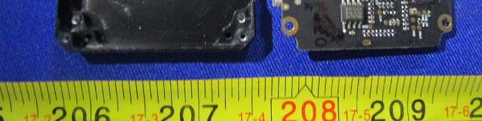
Partial View of Internal PCB and Enclosure
A glance at the partially disassembled SRW-60G reveals a dark, high-density PCB nestled within a precision-molded enclosure. The visible integrated circuit, packaged in a QFN or similar form factor, likely serves as an RF transceiver or microcontroller—positioned strategically near the board edge for optimal signal routing. The fine-pitch traces, abundant vias, and ground pours reflect meticulous attention to signal integrity and EMI suppression, essential for stable mmWave operation. While no clear antenna is visible in this crop, subtle unpopulated pads near the edge hint at provisions for a PCB trace or external antenna connection, consistent with the device’s wireless video transmission role. The visible passive components and a crystal oscillator indicate robust clocking and RF management, all within a compact, mechanically secure assembly.
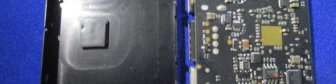
Densely Populated RF/Digital Board with Shielding
Examining a broader section of the PCB, the design sophistication becomes even more apparent. Multiple ICs in QFN, TQFP, or BGA packages cluster around a central area, likely comprising the device’s core SoC, RF transceivers, and supporting memory or power management chips. The board-edge connector, with its high pin count, suggests support for high-speed video, power, or control signals—crucial for modular integration. EMI/RFI shielding is robust, with a removable shield can enveloping the most sensitive RF sections, minimizing both emissions and susceptibility to external interference. Inductors and capacitors are strategically placed for localized power regulation, supporting the noise-sensitive digital and RF circuits. Overall, the dense component placement, modular shield, and careful via strategy underscore a professional-grade RF/digital design, optimized for 60 GHz wireless video transmission.
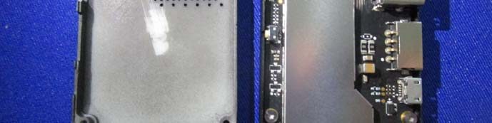
Shielded High-Frequency Section with Modern Connectors
A focused view of the device’s shielded internal section highlights the commitment to RF integrity. The substantial metal shield, now removed, previously covered the majority of the PCB, protecting critical RF and high-speed digital circuitry. The black ENIG-finished PCB is densely populated, with fine-pitch traces and evidence of controlled impedance routing. The presence of a USB Type-C connector affirms support for modern power or data interfaces, while smaller FPC/FFC connectors enable flexible internal connections. Large capacitors and inductors near the USB port handle local power conditioning, essential for stable high-frequency operation. The modular yet robust construction, combined with extensive EMI shielding, ensures reliable performance in demanding wireless video transmission scenarios.
PCB Section with Large IC and FPC Connector
A close-up of another PCB segment reveals a large, black, rectangular IC—potentially the main processor, RF transceiver, or onboard memory—flanked by densely packed passive components. The black soldermask and multi-layer construction point to a high-quality, space-efficient design. A small FPC/FFC connector near the center is likely used for peripheral connections, such as additional antenna modules or control interfaces. The strategic placement of ground pours and stitching vias ensures optimal EMI containment and signal integrity, vital for the high-speed, high-frequency data handled by the SRW-60G. The overall layout reflects modern best practices for compact, high-performance wireless devices.
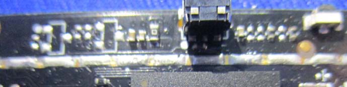
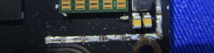
PCB Close-Up with Controlled Impedance Traces
This detailed view highlights the nuanced engineering of the SRW-60G’s PCB. Distinctive trace geometries—such as wide, curved traces—suggest controlled impedance routing, likely for RF or high-speed digital signals. The visible ground pours, via stitching, and large plated-through holes reinforce a commitment to EMI control and signal integrity. The green/gold edge component may serve as a test interface or high-density connector, while yellow MLCC capacitors provide local decoupling. The absence of visible ICs in this section shifts focus to the board’s RF layout, emphasizing the importance of trace design and grounding in 60 GHz wireless operation.
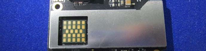
Shielded BGA Section for High-Speed RF Processing
A final internal image showcases a section of the PCB dominated by a large EMI/RFI shield can, with a cutout revealing a BGA footprint underneath—indicative of a high-density, multi-function IC such as an SoC or RF transceiver. The surrounding passive components and fine-pitch traces suggest this area is the heart of the SRW-60G’s wireless processing capabilities. The robust via stitching and extensive ground planes ensure minimal RF leakage, supporting both regulatory compliance and optimal performance. This region epitomizes the device’s focus on high-speed, low-latency wireless data handling, enabled by sophisticated component integration and shielding.
Regulatory Insights & FCC Filing
The SRW-60G’s registration under FCC ID SS3-60RX1604 signifies full compliance with US electromagnetic interference (EMI) and radiofrequency (RF) emission standards. This certification, managed via FCC.gov, is a prerequisite for legal sale and operation of wireless devices in the United States. While the grant date is listed as “None,” the presence of this FCC ID confirms that the device successfully underwent rigorous testing to demonstrate adherence to FCC Part 15C1 rules.
FCC filings for such devices typically include:
- RF Exposure Reports: Ensuring user safety regarding electromagnetic emissions.
- EMC (Electromagnetic Compatibility) Test Reports: Verifying the device does not cause or suffer from unacceptable interference.
- Internal & External Photographs: Documenting hardware design and build quality.
- User Manuals: Outlining safe operation, setup, and regulatory notices.
- Schematics & Block Diagrams: Detailing the device’s electrical and functional architecture.
This structured documentation not only protects end-users but also provides transparency and confidence to integrators, resellers, and regulatory bodies regarding the device’s conformity to stringent technical and safety standards.
Potential Use Cases & Target Audience
Despite the absence of a formally specified target audience, the SRW-60G’s advanced features and robust engineering make it ideally suited for several demanding scenarios:
- Professional Aerial Cinematography
- Enables real-time, high-definition video downlinks from drones to ground stations, allowing camera operators and directors to monitor and adjust shots with minimal latency.
- Live Event Broadcasting
- Facilitates untethered, high-bandwidth video transmission for sports, concerts, or news events, replacing traditional cabling and providing greater mobility for camera crews.
- Industrial and Security Monitoring
- Supports wireless, high-resolution video feeds in factory automation, remote inspection, or surveillance applications where wired connections are impractical or impossible.
These use cases highlight the SRW-60G’s appeal to technical professionals—cinematographers, broadcast engineers, and industrial integrators—who demand reliability, performance, and regulatory compliance in mission-critical wireless video applications.
Conclusion
The SRW-60G by SZ DJI TECHNOLOGY (Model: 60RX1604) exemplifies the cutting edge of wireless video transmission technology. Its robust, multi-layer PCB, advanced shielding, and operation in the 60 GHz mmWave band enable high-throughput, low-latency video links demanded by professionals. The device’s registration under FCC ID SS3-60RX1604 underscores its compliance with US RF emission standards, ensuring both safety and legal market access. Whether integrated into drones, broadcast rigs, or industrial systems, the SRW-60G stands as a testament to meticulous engineering and regulatory diligence in the wireless communication landscape.