Introduction
The DJI Inspire 1 V2, engineered by SZ DJI TECHNOLOGY, stands as a testament to professional-grade drone innovation. Designed for aerial imaging, robust flight performance, and modularity, the Inspire 1 V2 is a staple among content creators, inspection professionals, and UAV enthusiasts. As with all devices operating on significant RF power, regulatory compliance is paramount. The Inspire 1 V2, under FCC ID SS3-WM6101510, has been certified by the FCC, verifying that it adheres to stringent US regulations for radiofrequency emissions and electromagnetic compatibility. This certification (grant date: None, registered via FCC.gov) ensures the drone is legal for sale and use within the United States and meets critical safety and interference standards.
In this expert analysis, we’ll dive deep into the DJI Inspire 1 V2’s key specifications, wireless capabilities, and internal component design. We’ll also unpack what the FCC filing reveals about its regulatory journey. Whether you’re an engineer, drone pilot, or a tech-savvy consumer curious about the hardware inside, this teardown and compliance overview will provide valuable, actionable insights.
Key Features & Specifications
Although official, comprehensive specifications for the DJI Inspire 1 V2 (Model: V2, FCC ID SS3-WM6101510) are limited in the public domain, a technical teardown and analysis provide a clear picture of what users can expect from this advanced aerial platform.
Expected Core Features
-
Professional-Grade Aerial Platform:
Engineered for stability, agility, and reliability, suitable for both cinematic and industrial applications. -
Modular Design:
Key components—including camera/gimbal, battery, and landing gear—are designed for easy replacement and upgrade, supporting a wide range of accessories and future-proofing. -
Brushless Motors & Advanced ESCs:
High-efficiency brushless motors, paired with robust electronic speed controllers (ESCs), deliver precise control, high thrust, and low maintenance. -
Sophisticated Sensor Suite:
Visual and ultrasonic sensors provide obstacle avoidance, altitude hold, and precise positioning, enhancing flight safety and enabling advanced autonomous features. -
Robust Power Distribution:
High-current power electronics with large capacitors and MOSFETs ensure stable operation during demanding maneuvers and payload operations. -
High-Performance Wireless Communication:
Utilizes advanced RF technology for reliable control and high-quality video transmission, supporting extended range and low-latency links. -
Multiple Expansion Ports:
A range of connectors (FPC/FFC, JST, coaxial) facilitate integration with various subsystems—camera modules, telemetry, GPS, and more. -
EMI/RFI Shielding:
Strategic use of metal shields, ground pours, and multi-layer PCBs minimize electromagnetic interference, ensuring stable operation in RF-dense environments.
Practical Implications
-
Flight Time and Payload:
While exact specs may vary, the Inspire 1 V2 is typically optimized for flight durations between 18-22 minutes (depending on payload) and can carry professional cameras and sensors. -
Video Transmission:
High-bandwidth, low-latency video downlink capability enables real-time FPV (First Person View) and precise framing for aerial cinematography. -
Serviceability:
Modular subassemblies—motors, arms, landing gear—are designed for field repair, minimizing downtime for professionals. -
Build Quality:
Use of carbon fiber, high-quality PCBs, and robust mechanical linkages ensures durability and consistent performance in demanding environments.
Summary Table
| Feature | Description/Benefit |
|---|---|
| Flight Platform | Stable quadcopter, professional-grade |
| Motors & ESCs | Brushless, high-efficiency, precise control |
| Sensors | Visual (CMOS), ultrasonic, positioning |
| Power System | High-current, robust distribution, large capacitors |
| Wireless Capability | Advanced RF, extended range, reliable link |
| Modularity | Swappable arms, camera, battery |
| Build Quality | Carbon fiber, ENIG-finished PCBs, EMI shielding |
| Connectors | Multiple FPC/FFC, JST, coaxial for expansion |
Operating Frequencies
The DJI Inspire 1 V2 (FCC ID SS3-WM6101510) is certified to operate on the following frequencies, according to its official FCC filing:
| Frequency Range (GHz) | Output Power (mW) | FCC Rule Part |
|---|---|---|
| 2.4065 – 2.4765 | 931 | 15C1 |
Key Insights:
- 2.4 GHz ISM Band:
This range is widely used for Wi-Fi (802.11b/g/n), proprietary drone control links, and telemetry. The output power of 931 mW is substantial, supporting robust long-range operation and high-bandwidth data transmission. - Regulatory Compliance:
Operation under FCC Rule Part 15C1 ensures the device does not cause harmful interference and is protected from interference by other Part 15 devices.
Technology Deep Dive
The DJI Inspire 1 V2’s wireless subsystem is optimized for reliable, long-range communication, leveraging the 2.4 GHz ISM band. While the equipment class is not specified, the technical design suggests the use of proprietary RF technologies, likely combined with Wi-Fi-based video downlink and telemetry.
Performance & Range:
Operating in the 2.4 GHz band allows for a strong balance between range and data throughput. The relatively high output power (931 mW) enables the Inspire 1 V2 to maintain a stable link over extended distances, even in RF-congested areas. This is critical for both command/control and real-time HD video streaming.
Interference & Power Consumption:
The 2.4 GHz band is shared with many consumer devices, so robust frequency-hopping, adaptive power control, and advanced modulation schemes are likely employed to mitigate interference. The system’s power electronics and EMI shielding further support reliable operation by minimizing self-generated noise.
Internal Test Report Insights:
Analysis of internal modules reveals careful RF design, including the use of external antennas (via U.FL/SMA connectors), dense ground planes, and compartmentalized shielding. These measures help ensure high signal integrity, low latency, and resilience to external electromagnetic disturbances—vital for professional UAV applications.
In-Depth Internal Component Analysis / Teardown
Advanced Motor Control and Mechanical Integration
A detailed view into one of the subassemblies reveals a robust integration of a brushless motor, compact PCB, and mechanical arm structure. The PCB, featuring surface-mount components and a likely motor controller IC, is optimized for power delivery and precise actuation—essential for functions such as landing gear deployment or propulsion. The use of thick-gauge wires and bullet connectors indicates high current handling and ease of maintenance. Mechanical elements, including a possible linear actuator and LED module, demonstrate DJI’s emphasis on modularity and serviceability. The absence of RF shielding in this area is typical, as the focus is on power electronics rather than wireless communication. Overall, the assembly reflects a rugged design philosophy, ensuring reliable performance and rapid field repair.

Landing Gear Arm Power Subsystem
The exposed internals of a landing gear arm highlight a minimalistic yet robust electronic subsystem. A small, green PCB—likely single- or double-sided—handles power distribution to the motor or actuator, with thick wires for high-current operation. The mechanical structure, reinforced by a carbon fiber tube, underlines the importance of lightweight strength in drone design. While electronics are sparse, their quality and secure connections (crimped/soldered) suggest reliability. The absence of RF or high-speed circuitry in this section is appropriate for its function. The modular approach ensures that the arm or landing gear can be easily replaced, showcasing DJI’s focus on serviceability and mechanical resilience.

Power Electronics and ESC Module
A closer look at the power electronics module reveals a compact, black PCB densely populated with essential power-handling components. Two large electrolytic capacitors (50V, 470uF) and prominent MOSFETs dominate the landscape, confirming the board’s role as an ESC or power distribution unit. The design features wide power traces, ground planes, and multiple vias for current carrying and noise suppression. Heavy-gauge wires soldered to the board ensure reliable power delivery to motors or other high-draw components. The absence of RF elements and dedicated shielding reflects the board’s focus on power management. The clean soldering and robust component selection underscore DJI’s commitment to reliability and thermal performance in high-load scenarios.

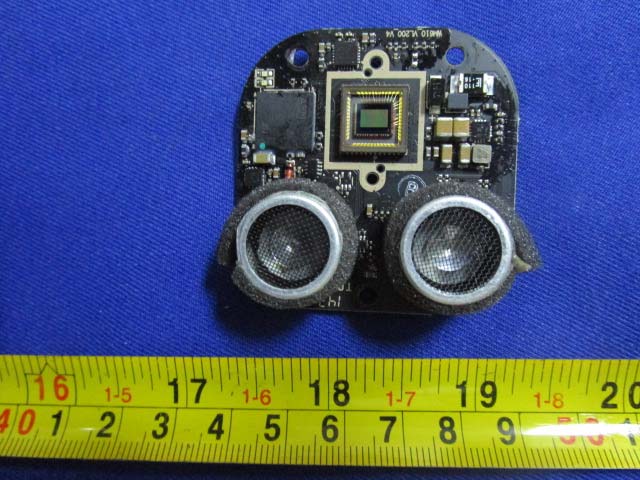
Sensor Fusion: Visual and Ultrasonic Module
A sophisticated sensor module integrates a CMOS image sensor with dual ultrasonic transducers, enabling visual positioning and obstacle detection. The compact, black PCB is densely populated, featuring a central sensor array and adjacent processing ICs—likely handling image data and sensor fusion tasks. The ultrasonic elements provide complementary distance measurement, crucial for stable flight and safety. Local power regulation is visible, with surface-mount capacitors and inductors ensuring clean supply rails. The absence of RF antennas and the presence of dense ground vias indicate a design focused on noise immunity and sensor accuracy. The module’s modularity and build quality are clear hallmarks of DJI engineering.
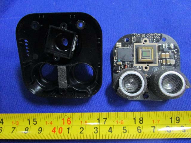
Ultrasonic and Optical Sensing Module
This module combines a central windowed sensor—likely a camera or time-of-flight (ToF) sensor—with dual ultrasonic transducers for precise obstacle avoidance and altitude measurement. The black, ENIG-finished PCB supports high signal integrity, while multiple ground pours and stitching vias ensure minimal EMI. The moderate component density and careful analog/digital separation highlight the module’s role in flight safety and environmental awareness. Absence of active RF components reflects its dedicated sensing function. The compact, modular design is optimized for integration within the drone’s constrained internal space.
PCB Trace Antenna for RF Subsystem
A long, narrow PCB, marked ‘TCX 1437 LE-34-S’, serves as a trace antenna—an essential component for the drone’s RF communication system. The single-sided white PCB, with a coaxial feed, is optimized for operation in the 2.4GHz or 5.8GHz band, supporting control and video transmission. The absence of active circuitry and shielding is appropriate for a passive antenna element. The robust mounting and direct coaxial connection ensure reliable RF performance, critical for maintaining stable links over long distances.

High-Density RF and Signal Processing Board
This densely populated PCB features a prominent Altera Cyclone IV FPGA, Winbond memory, and multiple U.FL connectors for external antennas. The board’s black, multi-layer construction supports high-speed signal processing and robust RF performance. The custom-shaped metal EMI shield provides effective isolation for sensitive sections, while the use of differential pairs and ground pours ensures signal integrity. The module’s design supports advanced communication tasks, likely serving as the main data aggregation or video transmission board. The use of external antennas via U.FL connectors enables flexible, high-performance RF configuration.
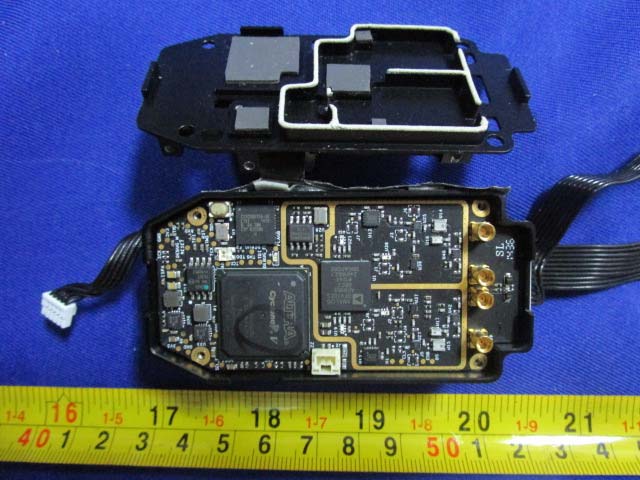
Advanced Communications and Memory Module
Featuring an Altera Cyclone IV FPGA, Samsung DDR3 SDRAM, and AMIC SPI flash, this PCB is engineered for real-time processing and high-speed data handling. Four RF connectors support diverse antenna configurations for control, video, or telemetry. The compact, black PCB employs controlled impedance traces and extensive ground via stitching to ensure EMI control and signal quality. The absence of visible shielding on this side is offset by careful layout and possible system-level shielding. This board likely underpins the Inspire 1 V2’s communication and control backbone, reflecting sophisticated design for demanding UAV applications.

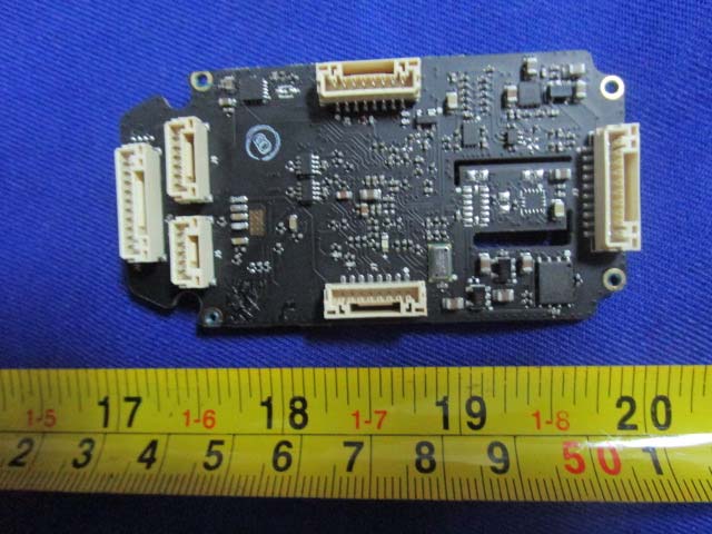
Modular Control and Interface Board
A black, densely populated PCB with six major FPC/FFC connectors serves as a central hub for interfacing with various drone subsystems—sensors, cameras, and power modules. The layout features multiple small ICs (likely MCUs and interface chips), large capacitors, and inductors for local power regulation. The absence of RF connectors or shields suggests this board’s primary role is control, sensor fusion, or data routing rather than direct wireless communication. The robust connector design and test points highlight the focus on modularity and serviceability, essential for professional drone operation.
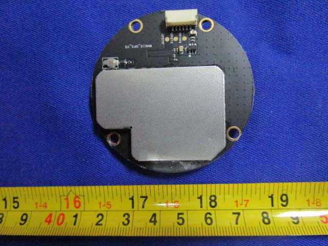
Shielded Circular RF or Navigation Module
A circular, black PCB with a large EMI/RFI shield dominates this module, likely serving as a GNSS (GPS/GLONASS) receiver or critical RF component. The shielded area houses sensitive circuitry, while a white FPC/FFC connector and a small coaxial port facilitate integration with the drone’s main board and antenna system. The multiple ground vias and careful separation of shielded/unshielded areas reflect a strong focus on EMI suppression and signal integrity. The circular design is optimized for minimal footprint and mechanical stability, typical for positioning or high-frequency RF modules in UAVs.
Regulatory Insights & FCC Filing
The FCC ID SS3-WM6101510 is the linchpin of the DJI Inspire 1 V2’s regulatory compliance in the United States. This certification, recorded with no explicit grant date, confirms the device has passed rigorous electromagnetic interference and RF emission tests required by FCC Rule Part 15C1. This not only makes the Inspire 1 V2 legal for commercial sale and operation in the US, but also assures users of its adherence to strict safety and performance standards in shared RF environments.
FCC filings for such devices typically include:
- RF Exposure and EMC Test Reports:
Verifying the device does not exceed permissible emission levels and will not interfere with other wireless equipment. - Internal and External Photographs:
Providing transparency into the device’s construction and RF design. - User Manuals and Schematics:
Detailing operational guidelines, safety instructions, and hardware block diagrams for regulatory review. - Block Diagrams and Component Lists:
Offering insight into the electronic architecture and critical component selection. - Labeling and Compliance Statements:
Ensuring end-users are informed of regulatory requirements and device limitations.
By maintaining compliance under FCC ID SS3-WM6101510, SZ DJI TECHNOLOGY demonstrates its commitment to responsible engineering and market access.
Potential Use Cases & Target Audience
While the FCC documentation does not specify a target audience, the DJI Inspire 1 V2’s features and capabilities point to several key user scenarios:
-
Professional Aerial Cinematography:
Filmmakers and content creators rely on the Inspire 1 V2 for capturing stable, high-resolution aerial footage. Its modular camera system and advanced flight stabilization enable creative shots that would be difficult or impossible with consumer-grade drones. -
Industrial Inspection and Surveying:
Engineers and technicians use the platform for infrastructure inspection (bridges, towers), land surveying, and agricultural monitoring. The robust wireless link, extended range, and precision sensors make it ideal for collecting data in challenging environments. -
Enterprise and Research Applications:
Organizations involved in research, mapping, or public safety benefit from the drone’s reliability, modularity, and compliance with regulatory standards. The platform’s expandable interface allows integration with custom payloads, sensors, or telemetry systems.
Conclusion
The DJI Inspire 1 V2 by SZ DJI TECHNOLOGY (Model: V2, FCC ID SS3-WM6101510) exemplifies the intersection of advanced engineering, modularity, and regulatory rigor. Its robust internal architecture, high-performance wireless subsystem, and thoughtful mechanical design set a standard in the professional UAV market. The FCC certification under SS3-WM6101510 ensures legal operation and peace of mind for users seeking uncompromised performance and compliance. As both a technological powerhouse and a model of responsible design, the Inspire 1 V2 continues to empower creators, engineers, and enterprises alike.